Wednesday, May 20, 2015

Direct Current Circuits And Resistance


Purpose:  We introduce direct current circuits. We also introduce the idea of resistance, how to orient them and how to measure this orientation.

Circuit 1


Professor Mason begins by demonstrating two kinds of circuits with light bulbs attached. The first is a circuit with a switch at the center wire and the center wire also has a light bulb. The other two light bulbs are are a part of a circuit of one loop when the switch is open and these light bulbs are hooked in series as well as the batteries. The light bulbs in series are on due to the power supplied from the battery. The question is, if we close the switch, will the light at the center turn on. We find that it does not because the potential along the center wire is zero and with no potential, no power to light the bulb.
Circuit 2


In the second circuit, we have the two light bulbs connected in series when the switch is open. The question is, what happens when the switch is closed, introducing a new battery? We find out that the batteries do not change their brightness. This is because the potential drop remains the same, therefore, the power supplied to the bulbs do not change.

Summary Of the Circuits


Our board summarizes what occurred with the light bulbs when we closed the switch, which is no change.

The Introduction Of Resistors


On the top left corner of the board, we make a list of the ways we can configure the light bulbs and the batteries to make the lights dim or bright. We conclude that the brightness is dependent on the voltage and the current. We, then, introduce resistors in series connected to two power supplies in series. We do this to see how the resistance adds up in series. When we measure the resistance using the multimeter, we find the total resistance of the resistors in series is just the sum of the resistors.

Resistance In Parallel


Next, we connect the two resistors in parallel and measure the total resistance. The inverse of the total resistance turns out to be the inverse sum of the resistors.


In the lab manual, we document all of the voltages and current across the two orientations of resistance done previously. We find that the current splits into two smaller current after the first junction and the sum of the two smaller currents is equal to the initial current. If there are no junctions, the current is that same throughout and this current is dependent on the amount of resistance in the circuit.

Reading The Resistance Of Resistors


On the left hand side of the board, there are a bunch of resistors. These resistor have color markings on them so that a person can determine the resistance. The way to do this is to find the initial color and final color. The final color will determine the tolerance of the resistance while the color next to it is called the multiplier. This multiplier just multiplies the number received by the initial colors. The initial colors indicate single digits that determine the magnitude of the resistance and this is multiplied by the multiplier if it is larger by 10n times the digits found.

Finding The Equivalent Resistance


To get the hang of finding the equivalent resistance, we start off by finding equivalent resistance of a simple orientation of resistors.


In this image, the resistors are oriented more randomly. The key here is to find equivalent resistance of parts of the circuit, until it looks like a simple parallel or series orientation. For example, we start by looking at the top left parallel wires. We know how to add parallel resistors but we can only do it if the is one representation of resistance on each wire. We get this single representation by first finding the single representation of the two resistors in series, then, we find the equivalent resistance of the parallel wires. We keep doing this, little by little, until we had a single resistance that represents all of the resistors.

Conclusion:  We found that the key to a light bulbs brightness depends on the potential difference as well as the current, which is the power. This is proved by the first two circuits, especially the first. Our group believed the the middle bulb would turn on because flipping on the switch would introduce current. But the potential difference turned out to be zero and this causes no power to be supplied. We found out how to read the resistance of a typical resistor. These values are determined using colored strips. We, also, found a way for getting the equivalent resistance of any orientation. This is important because it allows us to get the desired resistance using a multitude of fix values of resistors.

Electric Potential


Purpose:  We, further, go into the concept of electric potential by going over some examples that are different than just two point charges. We, also, go into some hands-on activities for electric potential.


Potential Of A Charged Ring


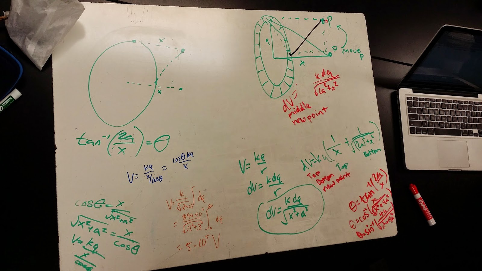
To begin our first potential problem, he had a ring with some charge on it. We then knew the variable dimensions of the ring and the potential point we are trying to find. The first point is in the center of the ring at some x distance away. We, then, start with the standard equation for potential, but this only applies to point charges. We alter the equation by saying the change in our potential is proportional to the change in q. After, we integrate to find the potential.

Potential Of A Charged Ring At A Different Location


Next, we use the same ring to find the potential at a different location. The twist here is that the location is positioned where it is difficult to take advantage of symmetry because the point is positioned at the top corner of the ring at some distance away. The key here is getting the proper distance that the point is from the ring. Using geometric representations, we are able to find that it is an x distance away from the ring and if a is the radius of the ring, we can say that the potential changes as the a distance increase and decreases.It increases and decreases because as we are taking infinitesimally small segments of dq, we integrate around the ring. This changes the a value. We can express this in terms of the change in the angle and solve for the potential.

Finding Potential Using E-Field


We work with the first problem of a charged ring and find the potential at a point x away from the ring centered in the middle of the ring. This time, we solve for the electric field the charged ring produces and use the definition for potential to solve for the potential of the ring at that distance. By definition, the potential difference is equal to the negative integral of the dot product of the electric field and the distance from infinity to the distance. When we solve for the potential this way, we get the same conclusion we saw before.

Using Excel To Find Potential


We continue with a different problem that is similar to the ring. This time, we have a wire of the length and solve for its potential and distance above the wire at the center of the wire using an excel spreadsheet. We decided to break the ring into 20 segments. We, then, solve for the potential at a segment using the center of the segment as the point charge. Once we have the potential of one segment, we multiply by the number of segments. This gives us nearly the same numerical value for potential of the ring.


We continue to solve for the same wire problem but we approach it differently. Instead, we look at the change in the radial distance and the potential it has throughout this change. This is very similar to the integral method. Once we have the potentials at every distance, we add up all of the potentials and in the end, we and up with the same answer we received from the previous excel sheet.

Potential By Integration


We can find the potential of a wire at any distance above it using the integral method. We determine the the y component does not change but the x does. We the write of an equation for the potential that expresses the change in the x direction. If we know where the point we are looking for is positioned with respect to the wire, we can easily solve for the potential using integration with the correct integration bounds.

Finding Potentials Along A Dipole


We start a hands-on experiment for finding the potential. We use a piece of conducting paper and this paper is nailed down to some insulating material. The nails are given an opposite charge and this creates a dipole along the conductive paper. Using the red and black pins, we are able to measure the potential at any point with respect to one of the charges.


This is how we set up the experiment. We hooked up our nails to some power supply. We, then used the multimeter to measure the potential at any point on the conductive paper.


This image includes a summary of our findings for the experiment. After finding the potentials along the x-axis, we were able to find the potential difference as well as the work required to move a charge from one location to the other. Finding the work just requires us to find the potential difference and then multiplying by the value of the charge we are trying to move. This is consistent, as energy is equal to the potential times the charge.


We found that as the radial distance approaches zero, we get infinite potential and as the radial distance approaches infinity, we get zero potential.

Conclusion:  We experimented with various ways to find potential from a distribution of charge. These methods include excel arithmetic and integration. Depending on the charged figure, it may be easier to use an excel sheet to find potential. We, also, received a hands-on view of potential when we determined the potential at various points of a dipole. We conclude that potential is zero infinitely far away and infinite at the source.

VPython Potential Activity


Purpose:  The objective in this activity to to use the superposition principle to find the potential of any number of charges at any point on VPython.

Potential Of Three Charges In A Ring Orientaion


Using the VPython activity done in class, the next step was to find any potential at any position along a ring of test charges. As the picture shows, some of the potentials are cut from the view. This can be fixed by zooming in and out of the view. We can also scale everything so that it fits the window. I, also, change the potentials found in class and found them along a diagonal. The picture shows this diagonal of potentials at the center of the three charges. The three charges also have the same charge.


This picture shows my attempt at grabbing as many potentials in the view of the window as possible without zooming in or out. We can see that these potentials truly do form a ring.


This image shows potentials of three charges again, except the potential along the ring are at a greater distance. In comparison to the first image of potentials, we can see that this is consistent with the theory of potential falling at 1 over r. As the r distance approaches infinity, the potential approaches zero. The two pictures show that as I increased the radius of the ring, the potentials decreased.


This image shows the first part of the code for the potential finding program. This code merely states some of the given values that I later implement in the program to find the potential. The  first three charges are created and put into position. The I began to find the potential along a diagonal. To do this, I had to use super position. This means I had to find the potential of each individual charge at the position that I am looking for the potential for and once these potentials are found, I add them to find the net potential. The formula for finding the potential is a bit straight forward. It consists of plugging in the given values, but the key here is to get the proper position. To do this, we just take the difference in the positions of the test point and the charge and this gives us the radius.


This image is a continuation of the other two potentials along the diagonal. It is the same programming as the first, except the position is altered.


The final part of the program involves the configuration of finding the potentials along a ring of test charges. This can be done by repetition an n number of times or it can be done using a loop. To avoid confusion of positions of various potentials, I created a while loop to find the potential around the three charges. The loop was set up so that it places a test charge in 36 different positions, forming a ring. The loop stops once it reaches a rotation of 2 pi radians, or one complete revolution. The loop, if set up correctly, guarantees to find these potentials along a ring, preventing likely error from 36 repetitions of finding potentials.

Conclusion:  We see that VPython, again, proves to be a useful tool in determining a visual and numerical representation for something that is difficult when done on two dimensional paper. VPython was able to give us a great representation for the potential of three charges. We can make some alterations with the programming and add another charge at any position. We can also see that the program seemed to work fine if we altered the radial distance of the ring, as the potential began to fall. In the end, superposition helps us find the potential.

Tuesday, May 12, 2015

Introduction To Electric Potential


Purpose:  We continue to look at basic circuits involving light bulbs. When, then, go into the general ideas of potential. We will see how potential energy, which is measured in joules, is related to the electric potential, which is measured in joules per coulomb.

How Bright Are These Bulbs?


We begin by developing a way to get two sets of light bulbs to be the brightest they can be by using two batteries and three wires. We found that running the batteries in series while running the bulbs in parallel is the most efficient way to distribute an equal amount of power to the bulbs and make it bright at the same time. The trick with using only three wires was that we had to come up with a way to make the bulbs parallel in a circuit. We did this by connecting two wires from the power supply to each bulb and have the metal next to the bulbs without wires connected touch. We, then, connect a single wire to the touching metal and connect it to the other end of the battery, closing the circuit.


The second experiment had us create a circuit that would make the light bulbs dim as possible. We found the connecting the batteries in parallel and the bulbs in series worked best.

Terminology


The white board shows what our circuit looks like drawn, without the proper format on the top left corner. On the top right corner, we are introduced to some symbols that represent some of the common things we will use in circuits. The bottom is the proper way to draw the two circuits we drew in the top left corner.

Heating A Cup Of Water


We take a look at how temperature changes as we heat water. The heating is caused by the power supply of some constant amount of volts. The next question we are given is: what happens the the change in temperature if we double the voltage?


Our group initially predicted that the slope for the change in temperature would just double. As it is seen on the graph produced on Logger Pro, the slope increased by more than double.

Why Is the Slope More Than Double?


We find that if we look at the relationship between voltage and current. We see that if we double the voltage, we double the current as well. Next, we know that the change in temperature is the same as saying heat going into the system per second, which we can say is power since power is joules per second. We, then, look at the relationship between power, voltage, and current. Since current doubles when voltage doubles, the doubles multiply together equating to four. Therefore, doubling the voltage gives us four times the power.

Reviewing Work


We go over a traditional problem involving work found in mechanics. We are to determine the amount of work done going up a slope. We found that there is no work done in the horizontal component but there is work done in the vertical component. This means that the work is independent of path. 

Work Done Using E-Fields


We apply what we know about work to problems a little more relevant to our class. We compare the work done by three different paths. One path goes in the direction of the E-Field, another path goes at an angle, and the third path goes perpendicular to the E-Field. Every path, also, has the same length. We determined that the path parallel to the E-Field does the most work while the path perpendicular does no work at all. The reason the path A does the most work is because the E-Field produces a force in the same direction as the E-Field and because the path parallel to the force, it produces the most work. The other paths need projections of the path in the direction of the force or cannot be projected.

Deriving Electric Potential From Potential Energy


In finding the potential energy a charge contains in reference to another charge, we used the idea of the integral of force dotted with dr (or some distance). We know that potential is measured in joules per coulomb. So, we can say that we can integrate the electric field dotted with dr. This gives us a fundamental equation for electric potential. This is consistent, as potential energy is very similar to the electric potential, except potential energy has the second charge multiplied.

Potential Of Two Point Charges


Before we began the VPython activity, we had to make sure we understood how to get the potential of charges at some point with a test charge. We started with something simple on the same axis. We found the potential using superposition.

Finding Potentials At different Points


Using VPython, we were able to create three spheres with some charge. We placed these spheres in an x-y plane and created a formula that allowed us to put a test charge and some random location and find the potential due to all the charges in the vicinity. Finding the potential was just a matter of applying the superposition principle to potential of n amount of charges.

Potential Between A Positive And Negative Charge


If we are to determine the potential between two opposite charges, we find that the potential is zero in the central position between the two charges. This potential is zero across and infinite plane at the center. The potential is not zero outside this plane.

Collaboration vs. Plagiarism


The difference between collaboration and plagiarism is displayed on the white board. Having someone do the work and copying it afterward is considered plagiarism while working in a group to get a solution and then, later, doing it without help (one's own interpretation) is collaborative. 

Conclusion:   We began by discussing the appropriate ways to label circuits and these appropriate ways make things neater to better interpret how the circuit behaves. We discussed the best ways to brighten and dim two light bulbs using the minimum amount of tools. We, then began to see the relationship between power and voltage. We found that power increases four times when voltage is doubled. We, also, revisited the definition of work and established that work is path independent. We, then, applied the concept in our derivation of electric potential, where we integrated the electric field dotted with dr. We found that potential follows the laws of superposition. This make calculations easier. We ended the day with a VPython activity, where we created a program that would allow us to calculate the potential at any position using a test charge.

Sunday, April 12, 2015

Voltage, Current, and Resistance


Purpose:  In this lab, we investigate the behavior of current through a wire. We will determine how current flows through a wire. We will also determine what measurable variables factor in the flow of the current. A majority of the experimentation we be done using light bulbs, wires, an electroscope, and multimeters.

Lighting a Light Bulb


To start off, we are given the task of powering a light bulb using a battery, one wire, and the light bulb itself. The picture above demonstrates how we were able to light a light bulb. In a later picture, we will explain how this works.

Electroscope


Professor Mason introduces the electroscope. This device allows us to detect charge on an object by placing the charged object on the top sphere. The charge travels through the sphere, into the box, and inside the box lies two metal plates. The metals plate gain the same charge as the charged object that is placed on the metal sphere and this causes the metal plates to separate, thus detecting charge.

How Does a Light Bulb Light Up


In reference to the light bulb experiment above, we demonstrate how exactly the light bulb lights up. We see the on the top left, two examples are given for the proper way of lighting a light bulb. We connect a wire at one end of the battery and the other end of the wire to the side of the metal screw on the light bulb. Then, we connect the bottom end of the light bulb to the other end of the light bulb, as shown. This is done in this manner because there is a filament inside the light bulb. one end of the filament is touching the screw end of the light bulb, the other end of the filament is touching the bottom of the light bulb. We will discuss more about how this works when we investigate the battery.

Investigating The Battery


We examine what would happen if we put the positive end of the battery on the electroscope. Nothing happened. We refer to the light bulb experiment. The reason the light bulb lights up is because there is current that flows through the bulb. The reason current is able to flow through the light bulb is because the electrons in the wire become attracted to the positive charge in the battery. This causes the electron to flow in the same direction. The battery contains a finite amount of energy and this energy allows for work to be done on the bulb.


Our picture shows what would happen if we use two light bulbs instead of one. It turns out that the light bulb shines much brighter. The more light bulbs used to power light, the more energy is available; therefore, more work is done to light the bulb.

Using An Old Ammeter


We begin to wonder whether the current in the light bulb is the same before the current enters the light bulb and after the current enters the light bulb. It may appear to make sense to some that there would be less current, since some less energy is used up when work is done to power the bulb.


Our group, on the other hand, predicted that the current would be the same before and after because we we believed that whatever flows in, must flow out at the same rate. Well, we see that the work done on the light bulb does cause the light bulb to take energy out of the system, but this doesn't influence the current. We wrote that power equals the voltage time the current and we see that the power is measured in joules per second. We also see that the voltage is measured in joules per coulomb. These two entities are reliant on the energy in the system, but the current is measured in coulombs per second. This is another way to see why the current does not change when energy changes. 

Finding Charge


We discuss the 4 variables we need to find charge. The cross sectional area can be viewed as the area of the circular side of a tube. Current would flow through the tube and it is the cross sectional area that is important in finding charge. Of course, the tube's cross sectional area does not have to be circular, it is just for relatable visualization purposes. The drift velocity is the velocity of the current of the electrons. 

Proportionality Of Current and Voltage


We start to set up our next and final experiment. This experiment will allow us to evaluate the relationship between current and voltage. 


Our group says that current and voltage are proportional to each other. We find that this is in fact true, but we know that when it comes to proportionality, there is a variable to account for. We find that this variable is called the resistance. We conclude that the voltage is equal to the current times the resistance, but we later realize that this is not always true. Some materials do not follow these predicable behaviors and, therefore, are not ohmic.

What Factors Into The Resistance


We take a look at some different pieces of wire and measure their resistance. We look at simmilar behaviors in length and other physical properties. We begin to see that the physical properties, do factor into the resistance. We find that the resistance becomes greater when the length or the wire increases, but becomes lower when the thickness of the wire increases. This can be explained visually and symbolically. If we look at the relationship between resistance, voltage, and current, we find that the current is reliant on the thickness and the voltage is reliant on the length. We also factor in the constant that represents the material.

Conclusion:  Using light bulbs, wires, and multimeters, we found relationships between current, voltage, and the resistance. We were able to do what Harvard graduates could not, which is power a light bulb with a battery and one wire, and we were able to use what we learned to explain how the battery is lit. We, also, found that the ohm's law isn't always ideal for calculating resistance, so we found a different way to do it using its physical properties.


Monday, April 6, 2015

Gauss's Law


Purpose:  In this lab, we take a look at some of the behaviors of electrical fields. To do this, we use Gauss's Laws to get an idea of the magnitude of the electrical field at a given distance from the charge. We will also take a look at various situations involving microwaves.

Cal Tech's Electric Field App


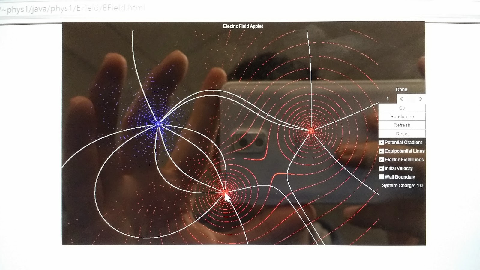
To begin, we take a look at a program, on Cal Techs website, that shows a visual representation of electric field lines between two charges. In this picture, we see two charges of opposite charge create symmetrical lines in between. This is very typical of dipoles. We can see the red point is surrounded by red circles. This is to show that the electric field shoots out radially. The same occurs with the blue point, but the electric field shoots inward instead of outward. The sum of the two electric fields at a given point is shown by the white lines.


This now shows the behavior of the electric field lines if another charge of the same magnitude is put in. We can see a repelling behavior between same charges and a dipole between opposite charges.

Redrawing the Field Lines


We re-draw one of the visual representations of the electric field lines and put arrows to display the direction of the electric field lines. The electric field lines of a negative charge point inward while the electric field lines of a positive charge point outward. We also draw some Gaussian surfaces and take the sum of these charges within these surfaces. After, we find the flux through the surfaces and calculate the net flux.

The Electric Field of a Conducting Cylinder


We utilize the vandegraff generator to distribute charge along a conducting cylinder. We were given the task to predict what would happen to the pieces of metal that hang inside the cylinder and outside the cylinder.


Before we find out what happens to the pieces of metal, we discuss the relationship between flux and charge. We write that flux and charge are proportional to each other. We also cover a little unit manipulation  and solve for the k value that multiplies charge to account for the proportionality between the two. It turns out the k was equal to one over epsilon knot. We then say that flux equals to the charge enclosed within the surface divided by the permittivity of free space.


Our group believed that nothing would happen to the pieces of metal that lie next to the conducting cylinder.


We find that our prediction of nothing moving is wrong, as the metal on the outside of the cylinder tries to distance itself from the conducting cylinder. The metal on the inside does not move. This is explained using Gauss's Law. There is no electric field inside the conducting cylinder but there is an electric field outside the cylinder. In the equation for flux, the charge enclose inside the cylinder is zero.

What Do Charges Do Inside Conductors?


We draw how eight charges behave inside a conductor. These charges look for the furthest distance apart. This means that they lie on the outer end of a cylinder. Charges are able to move, almost completely freely, within a conductor. We also discuss the the best possible place to be during a lightning storm. We say that it is best to be inside a car because the car acts as a Faraday cage, where a large portion of the charge flows through the car and into the ground. Some charge may enter the car, but if a person does not touch anything metal inside, a person should be safe, as electrical charge tries to flow through the outer ends of the metal.

What Happens If We Double The Radius?


We take a look at some arithmetic. If we double the radius of the circumference, the circumference doubles as well, but if we do the same for the area, the area increases by 4 times. This is because the 2 is also squared. The same goes for volume, which involves a power of 3.

What Happens If The Radius Is Halved?


We found that if we halve the radius, the volume goes to one over eight. We also see that we generally do not have to worry about the angle between the electric field vector and the area vector, as they generally point in the same direction, causing the angle to be zero and cosine of zero is one.


We take a look at the applications of Gauss's Law. We say that the charge density of an object with a small radius is equal to the charge density of an object with a large radius. We solve for the charge of the small volume and this gives us a relationship with a larger charge. Because we are looking at the small charge, we draw an imaginary Gaussian surface at the radius r and this gives us a surface area at radius r. The r's cancel and we get a simple equation for the electric field in terms of r and R. We, then start to look at a cylinder and its total surface area.

Electric Field Inside of an Insulator


We take a look at the electric field inside an insulator. We use the relationship of charge q and Q using charge density. With some substitution, we solve for the electric field inside an insulator in terms of the radius within the insulator.

Gauss's Law In Terms of Gravity


We took a different look at Gauss's Law by looking at it in terms of gravitation. We set the mass of earth over a constant k equal to the integral of Y dA. When we plugged everything in, we found that Y was equal to the acceleration of gravity.

Steel Wool in an Microwave


We start of the "what you should never do" by putting steel wool inside a microwave. Sparks flew and we were able to see that the electric field was strongest on the points as discharge was occurring on the points.

Fork Inside a Microwave


We see the same kind of effect that occurred in the steel wool happening to a fork. The tips of the fork began to light up, as the electric field was strongest there. This is because the charge density is highest at these points. We can draw a circle representing a sphere and place this circle over the points on the fork and we will see that there are more electric field lines passing through the surface area. The are "less" electric field lines passing through the same surface on the other end of the fork.

Compact Disk in a Microwave


Again, sparks occur on the CD because the CD contains some metal. Like the steel wool and the fork, the sparks occur where the electric field is highest.

Light Bulb Inside a Microwave


When we apply an electric field around a light bulb, the light bulb lights up and then changes color. It changes color because plasma is create when the temperature reaches a high temperature.

Conclusion:  We find that Gauss's Law helps us visualize how electric fields behave and this is easy using simple surfaces. We went into the changes of area and volume if we change the radius value. We, also, took a look at the electric field inside a conductor and inside an insulator. Inside a conductor, the electric field is zero. Inside an insulator, the electric field varies with position inside the insulator. To finish things off, we take a look at what happens when we get an electric field build-up on a metal. Build-up, generally, leads to sparks.