Thursday, June 4, 2015

R-C And L-R-C Circuits


Purpose:  In this experiment, we take a look at how circuits behave when we just use resistors and capacitors and then inductors, capacitors and resistors under a power supply that operates under some frequency. We examine the behavior of the current and the voltage using Logger Pro.


To begin,we go over the definition of impedance which is dependent on the resistance and the capacitive reactance. We can generalize the impedance as a quantity the behaves similar to a typical resistor. The impedance is defined by the variable Z. We look at Z like a resistor and apply it to Ohm's Law, where the voltage is equal to the current times the impedance. we take a look at this relationship and see what happens if we double our frequancy. We find, with a little algebra, that doubling the frequency will double the current.


We connect an A-C circuit together with a function generator, a capacitor, and an resistor. Using Logger Pro, we were able to measure the behavior of the current and the voltage. We, then, fit the lines generated. These lines are specific to the frequency of 10 Hz. We will later use these values to compare them to the theoretical values.


Like the previous graphs, we measure the behavior of the current and the voltage. The behavior of the current turned out "spikey". We fix this by running Logger Pro to only measure the current without the voltage and altered the measurements taken per second. After the adjustment, the graph was smooth and we fit the equation. The values of the fit equation will also be used later to compare with the theoretical values.


We create a table on the right corner specifically to compare theoretical impedance and experimental impedance. Our impedance is given by the equation on the left top corner and we used the theoretical values on the top to calculate theoretical impedance. We, then, used the values in the experiment, specifically max current and max voltage to calculate impedance. Our impedance is given by the equation in the bottom left where the current rms is equal to the max voltage divided by the product of radical two and the impedance. We just calculate the rms current and plug our values into the equation. We found that our theoretical values  for impedance was close to the experimental values at 10 Hz, with just a 3.6% difference. When we look at 1000 Hz, the difference between the impedance is much more substantial as our experimental gave us 39.2 and our theoretical gave us 10.13. This percentage difference was about 224%. The reason why there was a huge difference was because we start to have to account for the resistance within the power supply, which we can assume is around 50 Ohms.


We calculated the phase difference between the voltage vs. time graph and the current vs. time graph. To get this value, we look at the ratio between the difference between the inductive reactance aqnd the capacitive  reactance  and the resistance.


We finish this experiment by solving for the power dissipated. It is important that we look at the resistor when determining this, as the dissipation of power occurs at the resistor. The graph on the bottom left shows the point of the frequency, which is the maximum. We, also, complete our equation for impedance by factoring in the inductive reactance. The equation for impedance for series circuits is complete at the very top.

L-R-C Circuits


We finish by hooking up an L-R-C circuit. Using the values given, we calculated the current in the circuit and found the resonance frequency. This frequency occurs when the inductive reactance is equal to the capacitive reactance. Our is given in the middle of the board.

Conclusion:  We find that the when we calculate the experimental impedance, the values are off because we have to account for the resistance within the power supply at high frequencies. What we generally did was find the current along the circuit and used this current to calculate anything within the circuit because we only work with series circuits and we know that in a circuit in series, the current is the same throughout. With the current, we are able to find practically anything. We, also, go over the idea of resonance frequency. This happens when the inductive reactance and the capacitive reactance are equal and this is also the maximum frequency.

Alternating Current


Purpose:  We take a look at how a circuit behaves when the current switches directions periodically. We do this by examining the current and the voltage on Logger Pro and comparing the behavior of the two.

Derivations Of The Root Mean Square And Average Power

We do some integration to derive the values of rms voltage and current. The reason we determine these values is so that we are able to get a relationship between the maximum values and the rms. The relationship proves useful as the values detected by the equipiment used are root mean square values because in an alternating current, the average of the values proves to be zero so we use the rms, which makes all values positive to get an alternative average. We also come up with a definition for average power.

The Alternating Current Experiment


We put together a circuit using a circuit board. The circuit board consists of 3 resistors of different values, 3 capacitors of different values, and an inductor. We are only connecting resistors in the circuit in this case. The function generator serves as a power supply and we connect the currentometer and the voltometer to the circuit to measure the current and the voltage in the circuit. The measured values will show in Logger Pro. In this experiment, we use 100 Ohms.


When we record the current and voltage vs. time, we get a sinusoidal graph. Both graphs appear to be symmetrical. When we graph the current vs. voltage, the graph produced is linear. This is consistent, as the sinusoidal graphs show us that when voltage increases, current increases, and vise versa. We fit the lines to get a measurable function so that we may us the values of the function to compare to theoretical values. 


We summarize the experiment by comparing the values of theoretical rms voltage and current with the experimental voltage and current and find that the values were relatively close with percentages of 9.7%


We solve a problem with given values to solve for the maximum current. We used the definition of impedance to solve for the rms current and the rms current to solve for the maximum current.


The next experiment involves only a capacitor in a circuit. The resistor is not a part of the circuit. We see by the diagram on the top right corner shows a circular motion which say that the sine graph produced by the voltage graph is roughly 90 degrees from the cosine graph produced in the current graph, which makes sense that one is a sine and one is a cosine graph.


Our whiteboard shows the comparison of the experimental values to the graph values and the theoretical values. The large difference were by the comparisons between the experimental and graph values. This is due to large uncertainties in the data.


We do some derivations to find a function for the current. We do this by taking the integral of the voltage with respect to time. We find through our experiments that the voltage with respect to time is a sine function multiplied by the maximum voltage. When we integrate, we get that the current is the cosine times the max voltage and the negative inductive reactance. The orange writing shows more arithmetic for finding the rms current using the given values. The integral confirms what we saw in our experiments, that the phase difference is just 90 degrees.


The final experiment has us looking at just and inductor in a circuit. We take a look at the behavior of the inductor the same way we looked at the capacitor and the resistor. We find that the current vs. voltage graph produces an elliptical graph. This shows us that the phase difference is not at 90 degrees but somewhere in between 0 and 90.


We, again, compare the theoretical values to the experimental values. Shockingly, there was no difference in the values found. We, then, calculate the phase difference by examining the time differences in a period.

Conclusion:  We distinguish the behaviors of current and voltage of three different circuits with alternating currents and found that the graphs produce sinusoidal graphs which express that the current and the voltage is oscillating back and forth. The differences we seen is the phase difference in each. For resistors, the phase difference is 0 between the current and the voltage graphs. For the capacitors, the phase difference is 90 degrees. And, for the inductor, the phase difference was somewhere in between 0 and 90, which we found by examining the time difference within the period.

R-L Circuits


Purpose:  We start to look into circuits that only involve resistors and inductors and do some calculations.

Working With Inductors


We revisit how to interpret the resistance of a typical resistor with color coded brands. We were given an inductor in which we measure its physical values to determine its inductance. We also learned how to write in engineering notation. We also calculated the resistance of the wire and found the the resistance is negligible when calculating the time constant. From this time constant, we are able to find the period, as the time constant was about one fifth the period. From the period, we were able to get the frequency needed for the experiment that proceeds.

Using The Oscilloscope On The Inductor


We create a circuit using a resistor and an inductor and a function generator. Once we determine the frequency needed for this circuit, we set the frequency and connect the circuit together. We, then, connect the oscilloscope to the inductor so that we can see the voltage across the inductor. The graph behaves in a way that we expected it to, as it shows us the behavior of the induced emf inside the inductor. From the graph on the oscilloscope, we were able to get some experimental values to calculate the experimental time constant with uncertainty and with the time constant, we were able to get the number of turns the inductor has.

An R-L Circuit


We were given a circuit to examine with 2 resistors and an inductor. The circuit is as drawn on the white board. We had to find the currents in the circuit at a specific time. We know that the current changes when there is an inductor because of the induced emf but we see that one resistor has no inductor along that wire and therefore, we are able to quickly get the current along that wire. The current stays the same along that wire the entire time but when we look at the current where the inductor is located, we have to calculate current with respect to time. To do this, we need the max values for current. We use the max values to plug into our formula for current with respect to time when an inductor is present and this allows us to calculate the current along the wire with the inductor. The last thing for us to do was to calculate the time for our inductor to reach 11 volts. For that, we had to look at how many volts the resistor along the same wire would have if the inductor had 11 volts and calculates the current along that wire using ohm's law. Once we have the current, we can then refer back to our equation for current along the inductor and solve for time.

Conclusion:  We took a look at how the voltage and current behaves when we have an inductor and a resistor in a circuit. We found that if a power supply operates at some frequency, the voltage vs. time graph shows us that the induced emf starts at a large value and steadily decreases with time. Then, the induced emf switches "direction" because of the frequency being outputted. We use what we learned about R-L circuits to solve a problem.

Electromagnetic Induction


Purpose:  In this lab, we go into greater deteal on how electromagnetic inductance works. We, then, start to go into inductors and their applications.

Induced EMF


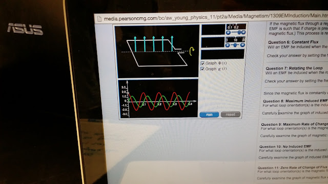
We begin to look at how the voltage behaves when the magnetic flux changes. We do this by examining an online program that graphs the behavior of the voltage or the emf as the magnetic flux changes. The website, also, has some questions that we would later answer. We can see that there is a correlation between that magnetic flux and the emf by the graph shown.


We answer the questions that the website had supplied. Overall, we conclude that there is a reaction when the magnetic flux changes. This reaction causes an induced emf which counteracts that change in the magnetic flux. We found that the change in the flux could be by the change in the magnitude of the magnetic field that passes through a loop, a change in the area of the loop, and the change in the orientation of the loop. We found that the induced emf is greatest the moment that there is no flux and that the magnetic flux changes most rapidly when the area of the loop is large. We see that the instantaneous change in the magnetic flux is zero when the area vector is parallel to the magnetic field vector (or the magnetic field is going the the largest possible area of the loop). When we examine this instant, we see that there is no induced emf. Therefore, we conclude that the induced emf is proportional to the change in the magnetic flux. Also, when observing the graph, we see that the induced emf the negative value of the change in the flux (if flux has a positive slope, induced emf is negative).

Movable Rod Acting As A Wire


Professor Mason sets up a circuit in which a rod acts as a wire that connected the two metal rails. We can also see that there is a magnet set up within the circuit. One of the rails are connected to a power supply and the other rail is grounded. 


We are able to see that the rod moves as there is a force acting on the rod. This is because there is current through the rod and this current is going through a magnetic field. This interaction causes a force on the rod that is perpendicular to the current and the magnetic field. The way the current flows dictates with direction the rod moves. We also see that the rod moving causes a change in the magnetic flux.


We proceed to expand on the experiment that Professor Mason had demonstrated and the ideas of the change in magnetic flux.


We find that as the bar moves at a constant velocity due to the magnetic force, there is a change in the magnetic flux. We found out, earlier, that the change in magnetic flux induces an emf. Our job was to find out how to find the induced emf. We were able to do this by examining the way the area changes. We know that the length of the rod never changes but the position of it does. We were able to see that we can write its displacement in terms of its velocity and the time the rod takes to travel the displacement. Multiplying this to the length of the rod gives us the change in the area in terms of the velocity, the time, and the length of the rod. We would later incorporate this with the definition of the magnetic flux, which is the magnetic field times the area. Since the area is changing, we get the change in the flux, which gives us the induced emf. In this case, the induced emf is positive as the area of the loop decreases because the rate at which the flux changes is negative, and we previously discussed that the induced emf has to be opposite of the change in flux. The induced current, then, tried to counteract the change in the magnetic flux with its own magnetic field. We know that a current generates a magnetic field in a cyclone fashion around the current. The direction of the magnetic field of the current is what counteracts the change in the flux. If flux decreases, the current flows in a way that generates a magnetic field to increase the flux.

Beginning Of Inductors


We do some derivations on the left side of our board involving inductors. We start off by writing the length of the inductor is equal to the negative potential across the inductor divided by the rate of the current. We, also, used the relationships between capacitance and charge to formulate the voltage across a capacitor as the current changes. As the current changes, the voltage does as well. In the middle, we work out a problem to find the inductance using the given physical parameters of the inductor. The inductance is found by the red formula by the number of loops, that area of the of the loop, the permeability, and the length of the inductor. We, also, derive the units of the inductance in the right side of the board.


On our white board, we discuss how inductors work. Inductors, generally, resist rapid changes in voltage.


We answer some final questions involving inductors and how they effect circuits.


We find that when we have an inductor in a circuit and run a current through it, there is an induced emf the opposes the emf of the battery. This is because the current generates a change in the magnetic flux through the loops and since there is a change in flux, there is a negative emf. The current vs. time graph shows us that the current increases to some maximum value and this is because the change in flux approaches zero as time goes by. This means that the current then becomes reliant on the power supply and the resistor in the circuit. We, then, find that the time for the current to hit equilibrium is dependent on the inductor as well as the resistor. Time increases and the inductor increases and decreases as the resistor increases. This is because if we have a larger inductor, a larger emf is produced and this causes the current to take longer to reach equilibrium. However, if we increase the resistance, we decrease the equilibrium value of the current which means the time to get to equilibrium is faster.

Conclusion:  We found that the induced emf was dependent on the negative change in the magnetic flux. We can change the flux by changing the area of the loop, orientation of the loop, and magnitude of the magnetic field. We, also, looked at how the flux changes in the experiment done by Professor Mason. We concluded that there is an induced current that generates a magnetic field to counteract the change in the magnetic flux. The direction of the magnetic field going through the loop and well as the way the area of the loop changes dictates which way the current flows. Finally, we took a look at inductors and the way they impact circuits. Inductors generate changes in magnetic flux which generates an induced emf. This causes the current start of at zero and reach equilibrium with time. This time was also found to be dependent on the resistor and the inductor.

Thursday, May 21, 2015

Induced Current


Purpose: In our experiments, we take a look at the effects of the change in the magnetic field. We will find that there are a wide variety of applications with the change in magnetic field.

The Force On Two Wires With Current


We begin by looking at how the two wires with current generate a magnetic field and this magnetic field influences the two wires by providing a magnetic force. We see that force is very small.

Induced Current


We set up a couple a wires connected to a machine that detects current. These wires a oriented in a loop or loops and we put a magnet inside the loops. We see that is the magnet just sits there, there is not current in the wires.


Professor Mason shows us that when we actually move the magnet through the loops, current is generated. This means that the change in the magnetic field induces current along the wire. Professor Mason demonstrates to us that the direction the magnet is moving or changing determines which way the induces current flows. 

Induced Current On A Coil Of Wire


We begin to apply the idea of induced current in a way the would help us to power a light bulb without a power supply connected directly to the loop of wires connected to the light bulb. We connect an AC power supply to a loop of wires which generates a magnetic field though the center. Since we are using an AC power supply, the current is always change causing the magnetic field to always change. This is essentially the same idea s moving the magnet back and forth. If we place the loop of wires that are connected to the bulb where the magnetic field changes, we can, essentially, induce current to power the light bulb without wires.

Induced Current On Metal Rings


We take another look into the induced current idea but see how this works with a metal ring. We find that current is induced in the ring in a similar fashion as the loops of wire that are connected to the light bulb. The current induced is in the opposite direction as the current in the loops underneath the current in the wire and, thus, generates a magnetic field in the opposite direction. This is the same idea as putting the same poles of two magnets together. They end up repelling but since the coil of wires connected to the power supply is fixed on the ground, the ring is the only thing that moves and it makes sense that is should move up.


We write four things on our whiteboard that can induce current. We can change the speed on the moving magnet, change the radius of the loops, increase the size of the magnet, or change the length of the wire.

Magnetic Race


Professor Mason shows us that a magnet going through a metal tube will induce current in the metal tube which will then generate a magnetic field. This magnetic field slows the magnet down significantly.


On our white board, we draw a representation of what is happening as the magnet is falling through the metal tube. We, also, write up a theoretical equation of the induced emf.

Conclusion:  The change in the magnetic field has a lot of practical use. We find the we can induce current in a loop of wire which could, ultimately, power a light bulb or charge and object. We take a look at how the current can generate a magnetic field around the wires which in turn creates a magnetic force on the wire next to it. We discussed how the current in a loop of wire creates a magnetic field at the center of the loop directed perpendicular to the circular plane. This is why our metal rings flew up. Finally, we discussed how a magnet through a metal tube feels a magnetic force from the induce current on the tube that generates a magnetic field.

Magnetic Fields Caused By Currents


Purpose:  We begin by look at the magnetic field generated by a wire with current. We, also, look into the effects of a current a wire in the presence of a magnetic field and how we can implement this with our electric motors.

Effects Of Heating A Magnetized Object


We discussed that there are two ways to demagnetize a piece of metal. One option was to simply hit the metal. The other option was to heat it until it is demagnetized. In some cases, like the video shows, demagnetizing an object may take a lot of heat.


On the right side of our white board, we indicate how magnets are magnetic and how objects that can become magnetic are not magnetic at the microscopic level. We drew little pill like figures that have their own poles and show how they are oriented when some object is magnetic and when some object is not. When something is magnetic, the poles all face in the same direction. We also discuss electric dipole moments, which is the potential for some some closed circuit to rotate with some torque.

Electric Motors


We begin to look at how electric motors work. We see that the rotation of the motors is dependent on the current in the wire, which is dependent on the the potential difference on the power supply. Our video shows that if we switch the wiring from the batteries. the current switches direction and the motor rotates in the opposite direction. This just proves that the magnetic force is dependent of the direction of the current and the direction of the magnetic field. The reason why the motor continues to rotate and not stop like in the previous lab is because the part of the motor that is allowed to rotate has a piece of circular metal at the center axis of rotation the is sliced in half. this means that they are essentially not connected. Each wire is connected to each slice and since the slice is made of metal, current is allowed to flow through it, as the motor rotates, the slices rotate as well and the fixed wires the touch the slices disconnect from the slice and proceed to touch the next slice. This causes the torque to remain in the same direction as long as current continues to flow out of the battery in the same direction.


Our next task was to create our own motor our of one magnet, a single wire, and some plugs to connect the single wire to the battery. We rolled the wire until it had a fair amount of loops and the loop was decently sized. This had to be accounted for because we know that the moment is dependent on the amount of loops as well and the area that the loops encompass.


In our whiteboard, we indicate how that magnetic field and the current effect the way the loop rotates on the motor used previously. The motor had two sides composed of loops and the current was flowing in the same direction. 

Looking At The Magnetic Field Around A Wire With Current


Professor Mason shows us that the current in a wire creates a magnetic field around in that flows in a circular motion around the loop. We find that we can use our right hand to find the direction that the magnetic field rotates by facing our thumb in the direction of the current. Our fingers end up showing the direction of the magnetic field. This is also shown using the magnets in the video.


Professor Mason demonstrates which direction the magnetic field is going in a wire that is positioned in an intricate way. We find that the magnetic forces can simply be added.


We discuss how the magnetic force and the electric force helps give rise to the speed of light constant. We also give a representative drawing of how the magnetic field rotates around a wire of current. The circle with a dot at the center shows us that the current is directed out of the board. We also start to get into Ampere's Law. This law allows us to find the magnetic field with the currents that generate the magnetic field. This law is very similar to the way Gauss' Law, which uses the charge to find the electric field.

Conclusion:  We discussed how heating up a magnetized metal can demagnetize it, It can also demagnetize with time and by striking the metal until it is demagnetized. We, also, discuss how we can create a loop of wire with current to rotate repeatedly so that we may use it as a motor. This is done by continuously changing the direction of the current of the loops so that it does not stop at 90 degrees like it did in the previous lab. Finally, we see that a wire with current also produces a magnetic field around the wire in a cyclone manner. We found that we can get the direction of the field using the right hand rule and that Ampere's Law makes it easy to find the value of the magnetic field.

Magnetic Field


Purpose:  We take a first look at how magnets behave and how the magnetic field lines look like. We will take a look at some of the fundamental principles of magnets and their relationships with moving charges. It will turn out that these guidelines will mirror what we saw in static electricity.

The Magnetic Field Lines Of A Magnet


Professor Mason shows us on a projector the behavior of the magnetic field lines on a magnet. This is done by using iron shavings. The iron shavings react to the magnetic field and basically give a visual representation of the magnetic field in 2-D. We see that the magnetic field, in a way, circles the magnet.


Our group makes an attempt on how these shavings look using arrows. This proves not to be a good representation for the magnetic field.


We alter the lines of the previous picture to give a better idea of how the magnetic field lines go on the magnet. The field lines actually create circular loops that go through the magnet. If the field lines go in one end of the magnet, they go out the other end. We call these ends, poles. One end is the North pole and the other end the South pole.

What Occurs When A Magnet Is Cut Into Two Pieces


When a magnet is cut into two pieces, we see that we do not create monopoles. Instead, the cut pieces because new magnets we north and south poles. Professor Mason demonstrates this by cutting a magnet.

Using Gauss' Law To Interpret Magnetism


We take a look at the idea used in Gauss' Law for drawing field lines to find the flux of the magnetic field. We see that the amount of lines that go out go back in. This means that the flux is always equal to zero.

Effects Of A Magnet On An Oscilloscope


Professor Mason demonstrates the effects a magnet has on an oscilloscope. We see the dot shift. The dot shifts according to the definition of the magnetic force, which is basically the cross product between the velocity the charge moves with the electric field.


We draw on our white board what occurs from a side view inside the oscilloscope. The horizontal line indicates the velocity of the beam. If we put a magnetic field across the beam, we can see that the force vector is perpendicular to the velocity vector and the magnetic field vector.


As an activity, we calculate the acceleration along the force axis. The cross product give us the force, and Newton's Second Law helps us attain the acceleration.

Motion Of A Moving Charge Under A Magnetic Field


Our board shows that if we have a charge moving at some velocity in a direction perpendicular to the magnetic field, the charge goes in a circular motion, as the force and the velocity continually changes.

Magnetic Force Along a Current


Professor Mason demonstrates that when we have a current running through a wire and this wires is exposed to some magnetic field, it will experience a force perpendicular to the length of the wire and the magnetic field.


After seeing the wire with current experience a force, we rewrite the equation for the force cause by the magnetic field in a way that describes a current carrying wire. The definition comes from the combination of the drift velocity and the number of charges contained within the wire. We run into the the definition for the current which replaces most of the variables that describe the wire.

Magnetic Force On A Circular Current


We see that if we have a circular current exposed to a magnetic field, the loop experiences a force that cause a torque. The loop does not continue to spin because after the loop rotates 90 degrees, the torque immediately goes the opposite direction. This cause the loops to spin 90 degrees and then stop.


The white board shows our prediction of what would happen to the loop when it experiences a magnetic field. We were right. We knew that there would be a counter torque, and while it is true that there is some angular momentum on the loop, the momentum is not large enough to keep the loop spinning.

Force On a Semicircular Loop


On excel, we are given the task to find the force that the loop experiences. We decide to approach the problem from a length of theta and calculate these individual forces. We know that the loop experiences the maximum force at the very top, as the vector length is perpendicular to the magnetic field. It has no force at the ends because the vector length is parallel to the magnetic field.


Calculating the different forces at different thetas gave us many forces in which we add to give us the net force that the loop experiences from the magnetic field.

Conclusion:  We discuss how magnetic fields behave and that there are no monopoles in existence. We also talk about how the movement of the charge and the direction of the magnetic field causes a force to be applied on the charge. This mirrors the ideas used in static electricity, where the force was dependent of a motionless charge and the electric field. We were also able to make a relationship for current and the force on the current. This idea is based on the fact that a current consists of many moving charges along a wire. Using the force of magnetism, we are able to apply the force equation to things that involve torque, which is fundamental to electric motors.